**We have a pack of some of the smaller parts**
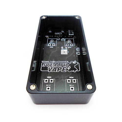
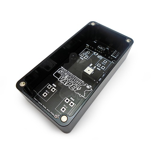
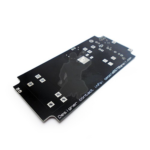
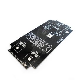
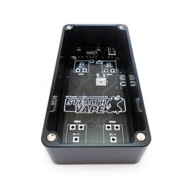
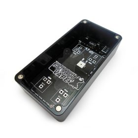
This printed circuit board is made for the Naos Raptor 120 watt module and fits in any Hammond 1590G-sized enclosure or larger. Building a raptor mod with this PCB fast and simple; just solder the components onto the board and drop the board into your enclosure.
Here are some links to components available from Mouser and Digikey
https://uk.mouser.com/ProjectManager/ProjectDetail.aspx?AccessID=63d531cb11
http://www.digikey.com/short/tz10v0
We’ll also have packs of components available in about a week.
In addition to the component lists or packs you’ll need the following components of your choice
- 18AWG wire
- 24AWG wire
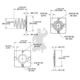
- 510 connector
- Volt Meter
- Potentiometer
- Fire button
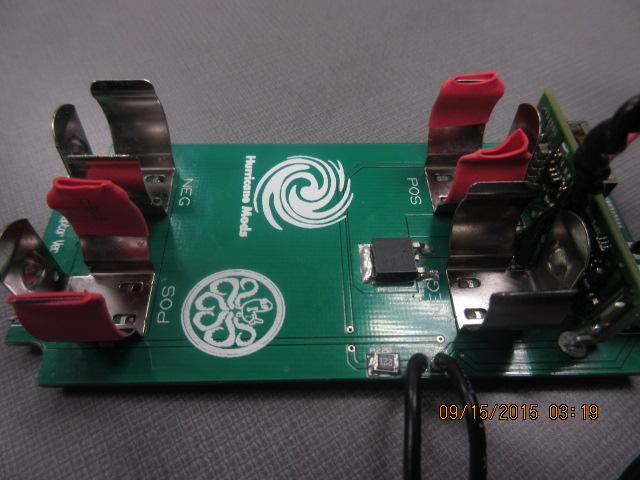
Lastly, Be sure to shrink wrap at least one of the inside arms of an upper and a lower battery clip to avoid any incidental contact. If you don’t do this, you will risk creating a short when installing batteries. No need to make sparks fly after all your hard work building your mod. I usually add red shrink wrap to the positive ends of the battery clips assembly to remind me which way to face my batteries, reverse polarity protection be damned.
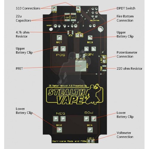
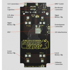
Building your DB Raptor Version 4 Printed Circuit Board:
What components do you need?
*use an equivalent part from another manufacturer if the one listed isn’t available
Component Part Number Manufacturer
1 Naos Raptor 20amp Power Module NSR020A0X43Z GE Critical Power
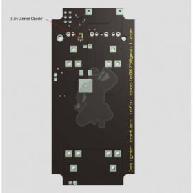
1 5.6V Zener Diode BZX84C5V6-7-F* Diodes Inc.
1 220 ohm 1/2W 1210 Resistor ERJ-14YJ221U* Panasonic – ECG
1 4.7 Kohm 1/2W 1210 Resistor ERJ-14YJ472U* Panasonic – ECG
1 DPDT Slide Switch ASE2E-2M-10-Z Copal Electronic
1 P-Channel MOSFET 30v 70amp IPD042P03L3 G* Infineon Technologies
2 22u MLCC 16v X7R 1812 Capacitors C4532X7R1C226M230KB* TDK
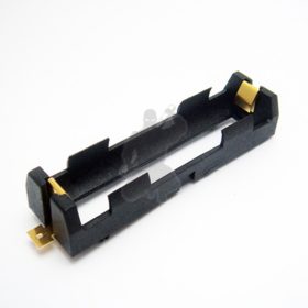
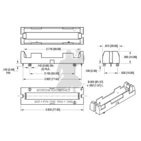
4 18650 Battery Clips 54 Keystone
What tools do you need?
*optional
A solder Iron with good clean tips (I recommend using flat sided D series and I series needle pointed tips)
Wire snips (for trimming wire, of course…)
Heavy-duty wire cutters (for trimming the pins on the raptor & the battery clips. I use 4″ end cut pliers)
A Dremel with cutting attachments or other rotary cutting tool*
A hot air rework gun*
Some thin flux core 63/37 solder (I like 0.015 inch Kester 44)
63/37 solder paste*
A roll of thin kapton heat resistant tape
Anti-static tweezers
A few acid brushes
A bottle Rubbing alcohol or PCB cleaner
Chemwipes (I got mine at an auto parts store)
Basic steps for soldering the resistors, capacitors and zener Diode:
First, it’s good idea to warm the PCB itself to room temperature as this will make all your soldering tasks easier. The solder pads are made of copper, so cold pads are a nightmare to work with. The zener diode on the back of the board is the smallest component. Installing it in place can be a pain. This is why solder paste is your best friend here. Dab the tiniest bit of paste of the all three zener pads and then hold the diode in place with tweezers. Lightly and quickly touch the soldering iron with a needle tip attached to the pads. A hot air gun can also be used to do this without having to hold to the zener in place. It can heat the paste enough to make it flow. Hot air could become your second best friend., If you don’t have a hot air station, a solder iron with a needle tip works just as well.
First thing you need to do is tin one side of the pads for each component. Since the 1812 capacitors and 1210 resistors are fairly large for SMD components, you may not need to use flux before applying the solder. Just use the tip of your iron to apply the flux cored solder directly on the pad. Tin your iron tip and quickly apply solder to the pad before the flux in the solder gets used up by the heat. Be careful not to add too much solder. All you should need to do is lightly touch to pad with a tinned solder tip.
Next, you need to tack down one side of a SMD component. Clean and tin your iron tip, but be sure not to add more solder to the pad. Then with the tweezers in one hand to pick up the component and lightly press it down against the tinned pad. With the other hand, touch the bead of solder on the pad with the iron tip. You should feel the component drop into place as the solder on the pad begins to reflow. If you have a steady hand, the component should lay completely flat. Don’t worry if it’s crooked on the pad so long as there is a solid solder joint between the pad and the component.
Lastly, apply a small amount of solder to the second pad and the other end of the component. You will probably need to rotate the board to do this easily. Just hold the iron tip so it touches both the component and pad, then lightly touch it with solder. Once again, make sure you clean your iron tip beforehand. You are melting flux core solder directly onto the pad to make a nice little solder joint, so extra flux shouldn’t be necessary. Be sure to use an acid brush dipped in a cleaning solution followed by clemwipes for clean up after.
Don’t worry if your solder joints aren’t shiny. Duller looking joints will work if you have good connection between the component and the pads.
Installing the Raptor
Solder the smaller components and the switch onto the board before you install the Raptor. Some of the SMD components are practically underneath the power module. It’s easier to deal with them first. The raptor module will fit loosely in through holes for the pins. Use kapton tape to securely stand the module up on the PCB, making it easy to flip the board over to solder the pins. Some of the pins will not be electrically connected, so you won’t need to solder all of them. However, trimming the pins down before soldering them will help the board lay flat in whatever enclosure you are going to use. Several of these pins are kinda thick, so you will want to break out your heavy-duty wire cutters for this.
Soldering the Battery Clips
It’s easiest installing these last. At this point, it might not be the worst idea to use heavy- duty cutters to trim the battery clip pins down or use a dremel to grind them down. You only need to trim the pins down about a millimeter. This will help with fitting the board into a 1590g-sized box. Make sure you leave enough of the each pin to completely fit into the through hole. The through holes for the battery clips are large. There will be a lot a play when you put them into place and they will fall out easily if you flip the board over. Use the kapton tape to hold them in place before you solder. Be sure to push the two bottom clips as far up and the two top clips as far down as you can when tape them onto the board. If you don’t, the gap between the upper and lower clips may be too wide and your batteries won’t make proper contact with them. Trust me, it’s a bitch to get these things back out to resolder them. Do it right the first time.
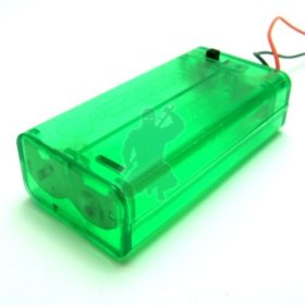
Don’t use solder paste to install these. That can get nasty. Flux core rod is best to completely fill the thru holes with a good solder joint. You don’t need to make large, mountainous solder joints to install these because those will only be a headache in the end. Remember, the inside height of a Hammond 1590g enclosure is only 21mm with lid on and your batteries will take up 18mm of that. You need all the room you can get.

Lastly, Be sure to shrink wrap at least one of the inside arms of an upper and a lower battery clip to avoid any incidental contact. If you don’t do this, you will risk creating a short when installing batteries. No need to make sparks fly after all your hard work building your mod. I usually add red shrink wrap to the positive ends of the battery clips assembly to remind me which way to face my batteries, reverse polarity protection be damned.
**Notes**
Any wire should be suitable for the voltage meter
Use 20AWG/g wire for the fire button,
Use 18AWG/g wire for the 510 + / –


Reviews
There are no reviews yet.